Pressure vessel heads, often overlooked, are crucial for efficiency and safety. For engineers, understanding head essentials is key. Let’s explore important aspects, such as dimensions, welding, and types in this article.
What Is a Pressure Vessel?
A pressure vessel is a container designed to hold gases or liquids at a pressure different from the ambient pressure, ensuring they remain contained and controlled. Think of it as a sealed vessel that keeps its contents under specific pressure conditions, used in various industries like oil and gas for safe and efficient operations.
Pressure vessels examples are glass containers, autoclaves, pressurized gas cylinders, compressors (including those used in refrigeration), vacuum chambers, and specially crafted laboratory vessels.
What Is Pressure Vessel Head?
A pressure vessel head, a major part that closes the ends of the cylindrical section, is a crucial component designed to hold gases or liquids under pressure. Think of it as the cover or top of the container. This head is like a protective barrier, keeping the contents inside and preventing them from escaping. It plays a vital role in ensuring the safety and efficiency of the pressure vessel.
Different types of heads, such as ellipsoidal, hemispherical, or torispherical, are used based on specific needs. In simple terms, the pressure vessel head is like the cap that keeps everything secure and contained, making it a key component in various industrial applications.
Pressure vessels have many parts, and the vessel head is a standout. Acting as a protective barrier, it keeps the inside separate from the outside. This section explains the role of vessel heads and how they impact overall performance.
Pressure Vessel Head Types
Not all heads are the same. We look at ellipsoidal, hemispherical, and torispherical heads, explaining their unique characteristics. Understanding these differences is important for designing vessels that work well.
1. Ellipsoidal Head
An ellipsoidal head, also called a 2:1 elliptical head, is a specific type of shape used at the end of a pressure vessel. The shape of this head is more economical because the height of the head is just a quarter of the diameter.
Picture the ellipsoidal head as a rounded, slightly flattened ball that closes off the vessel. The shape resembles an ellipse, which is like a stretched-out circle. Engineers choose ellipsoidal heads because this design helps distribute stress more evenly across the head, making it a reliable choice for containing pressure in various industrial applications.
2. Hemispherical Head
A hemispherical head, a head consisting of half a spherical shell and a straight edge (short section of a cylinder), is a rounded shape used at the end of a pressure vessel. Imagine it like half of a ball placed on top of the vessel. This design creates a dome or hemisphere, providing excellent strength and even stress distribution.
The simplicity of the hemispherical shape makes it effective in containing pressure. Engineers favor this type of head because it promotes stability and reliability in various industrial applications.
3. Torispherical Head
A torispherical head, a type of vessel head consisting of a dish with a toroidal section (spherical cap centered on the vessel) joined to a cylindrical section, is a specialized shape used at the end of a pressure vessel. It’s like a combination of a torus (a doughnut shape) and a sphere.
You can picture torispherical head as a section of a sphere with a torus added, resulting in a flatter, rounded end. This design offers a good balance between strength and cost-effectiveness. Engineers often choose tori spherical heads because they provide stability, even stress distribution, and are suitable for various industrial applications. In simpler terms, it’s a uniquely shaped end cap that contributes to the strength and efficiency of the pressure vessel.
4. Conical Head
A conical head, a shape used at the end of a pressure vessel, is a cylinder tapering to the bottom. It has a conical shell surface. Conical heads are also known as cone shells or tapered tank heads. Think of it like an ice cream cone turned upside down and attached to the top of the vessel.
This design forms a cone, providing simplicity and efficiency. Engineers choose conical heads for certain applications like vessel bottoms or cover plates because of their straightforward structure, making them suitable for containing pressure in various industrial settings.
5. Flat Head
A flat head, ideal for no-pressure applications, is a straightforward shape used at the end of a pressure vessel. As it is named, it is a type of pressure vessel head with flat surfaces. They are ideal for applications that require flat inside surfaces and are often used for low-pressure storage.
You can picture a flat head like a flat plate covering the top of the container. Unlike rounded heads, a flat head doesn’t have a curved or domed shape; it’s just flat. This design is simple and easy to manufacture, making it suitable for certain industrial applications. Engineers opt for flat heads when a more straightforward and cost-effective solution is needed for containing pressure.
5. Semi-Elliptical Head (SE)
A semi-elliptical head, often abbreviated as SE, is a specific shape used at the end of a pressure vessel; the head depth is four times the head width. Imagine it as half of an ellipse or a flattened circle.
Semi-elliptical design is commonly employed because it distributes stress more evenly, enhancing the structural integrity of the vessel. Semi-elliptical heads are suitable for various industrial applications where a balance of strength and efficiency is required.
6. Flanged and Dished Head
A flanged and dished head, a type of pressure vessel head that’s suitable for moderate pressure and height restrictions, is a specific shape used at the end of a pressure vessel. Picture it like a plate that’s slightly curved and has a rim around its edge.
The flanged and dished head design, with its flange (the rim) and dished (the curvature) features, offers both strength and versatility. It’s often chosen for pressure vessels requiring extra reinforcement or for those handling different substances.
Design Considerations
Designing an effective pressure vessel head requires careful thought. Things like pressure, temperature, and safety need to be balanced to ensure the vessel lasts a long time. Let’s explore these considerations in detail.
Stresses by Finite Element Analysis (FEA)
1. Cylinder and Hemi Head Tresca Stresses
|
Design Consideration |
Details |
| Code and Equations Used | ASME VIII-1 code equations are applied for Cylinders and Hemi heads. |
| Cylinder Stress (FEA) | For a ½” thick cylinder, the stress is 20,484 psi using FEA with a Tresca formulation. |
| Hemispherical Head Stress (FEA) | A 0.2474” thick hemispherical head results in a stress of 20,364 psi using FEA. |
| Comparison to Code Limit | Both stresses are very close to the ASME code design stress limit of 20,000 psi. |
| Discontinuity Zone Stress (FEA) | In the discontinuity zone of the head-to-shell junction, the stress is higher at 23,060 psi. |
| VIII-2 Code Allowances | ASME VIII-2 code rules permit stress increases over small distances and provide limits. |
| Acceptability of Stress | The stress in the discontinuity zone is deemed acceptable according to VIII-2 code rules. |
| VIII-1 Code Considerations | Beyond the requirement for a 3:1 taper, VIII-1 rules ignore these stresses based on practical experience. |
2. Cylinder and Hemi Head von Mises Stresses
|
Design Consideration |
Details |
| Tresca Stresses vs. VIII-1 Code Rules | Tresca stresses closely match VIII-1 code rules and measured FEA stresses for the cylinder and Hemi head by VIII-2 FEA methods. |
| Change in Von Mises Formulation | VIII-2 transitioned from using Tresca (P1-P3 stress) to von Mises formulation. Theoretically, von Mises stress results can range from equivalent to Tresca (P1-P3) to 15% lower. |
| Reported Stress Values | Von Mises stress in the cylinder is reported as 17,740 psi, 12% below the reported Tresca value. However, the reported stress in the hemi head remains at 20,322 psi. |
| FEA Requirements | FEA results must adhere to VIII-2 methods, including von Mises stress reporting. VIII-1 stress equations derivable follow Tresca methods. |
| VIII-2 Rules for Cylinder Design | VIII-2 has rules for designing cylinders that align with Tresca stress methods, allowing flexibility. |
| Thinner Cylindrical Shell in VIII-2 Part 5 | Designing VIII-2 Part 5 yields a thinner cylindrical shell compared to VIII-2 Part 4. As FEA methods gradually replace code rules, reduced cylindrical thicknesses will be observed, unlike hemi heads. |
| Transition to Von Mises Stress Reporting | The article adopts von Mises’s reported stress as VIII-2 has moved towards this formulation, though VIII-1 and VIII-2 part 4 still use Tresca methods. |
3. Stresses in SE & F&D Heads
|
Design Consideration |
Details |
| VIII-1 Formulation for 2:1 SE Heads | VIII-1 Formulation for 2:1 SE (Semi-Elliptical) heads results in required thicknesses equal to that of the shell. However, the code equation is not a predictor of actual stress. It is a design rule based on factors of safety, known to work in practice. Actual stress is higher in the knuckle region, equal to the design stress in the crown. |
| Nozzle Reinforcement in SE Heads | VIII-1 nozzle reinforcement rules account for higher stress in the knuckle region, requiring more reinforcement in that area. |
| F&D Head Stress Challenges | Flanged and Dished (F&D) heads, despite thicker construction, often have much higher stress in the knuckle region. Thinner F&D heads may exceed VIII-2 allowable stresses in the knuckle. Designers are cautioned about placing large nozzles in the knuckle region. |
| Challenges with Nozzle Pro Programs | Programs like Nozzle Pro may struggle to calculate nozzles in F&D heads due to them failing VIII-2 rules, even without added nozzle stress. While F&D heads are known to be safe, their required thickness might be higher if invented today. |
| Caution with FEA for SE and F&D Heads | Caution is advised when using FEA for the design of SE and F&D heads. Knuckle stresses can be in tension along the shell length but compressive in the radial direction. Thin knuckles may lead to buckling. |
| Expected Changes with Increased FEA Usage | With the increasing use of FEA methods, it is expected that F&D head thicknesses (for large diameter thinner heads) will be higher. SE head designs, on the other hand, are not anticipated to change significantly. |
4. Stresses in Flat Heads
|
Design Consideration |
Details |
| Stresses in Flat Heads | The VIII-1 formulas for flat heads result in heads with center section stresses calculated by FEA much lower than code rules allow. The flat head is in bending, with allowable stresses of 1.5x membrane, or 30,000 psi in this case. The actual center stress is half of this. Code rules focus more on the head-to-shell transition where an overbuilt head keeps the transition safe. |
| Focus on Head-to-Shell Transition | The code rules are more focused on the head-to-shell transition where an overbuilt head keeps the transition safe. |
| Freedom with VIII-2 FEA Methods | With increased freedom to use VIII-2 FEA methods in flat head design, thinner heads will be possible, with more thickness in the center than the edges. These thinner heads will exhibit more rotation at the head-to-shell junction, requiring careful attention from the designer. |
| Expected Reduction in Thickness | As FEA becomes more common in flat head design, thicknesses are expected to reduce, especially in the center of the head. |
FAQ: Understanding Head Essentials
1. How Does Head Shape Affect Performance?
The shape of the pressure vessel head affects how well it performs. For example, ellipsoidal heads distribute stress more evenly, making them more efficient.
2. What Materials Are Ideal for Vessel Heads?
Materials like stainless steel and carbon steel are popular because they resist corrosion and last a long time, ensuring the vessel stays strong.
3. Can Pressure Vessel Heads Be Customized?
Yes, customization is common. Engineers often adjust vessel heads to fit specific industry needs, taking into account what’s inside, the pressure, and the temperature.
4. What Safety Measures Should Engineers Follow?
Keeping things safe is crucial. Regular checks, following design rules, and meeting industry standards are important safety measures.
5. Are Ellipsoidal Heads Superior to Other Types?
Each head type has its strengths. Ellipsoidal heads are liked for how they distribute stress, but the best choice depends on what’s needed for a specific design.
6. How Can Innovations Enhance Head Performance?
Improvements in technology, like better materials and ways of making heads, can make them perform better, leading to more efficiency and durability.
In summary, understanding pressure vessel head essentials and designs is crucial for engineers in the oil and gas industry. This article has provided a detailed exploration, from its types and design considerations. By grasping the details of vessel heads, you can enhance your knowledge and contribute to safer and more efficient operations.
To further empower you in this field, consider enrolling in ASME Section VIII Div 1 and 2 training by PetroSync. This training program adopts a practical approach, incorporating real-world case studies to deepen your expertise. By participating in this course, you not only expand your theoretical knowledge but also acquire practical insights that are directly applicable to your work in the oil and gas sector. Stay ahead in your career and make a meaningful impact by investing in continuous learning and skill development.
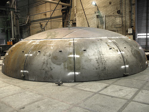
Credit header image: 2.bp

SEO specialist by day, fact-checker by night. An avid reader and content writer dedicated to delivering accurate and engaging articles through research and credible sources.

Business Development Manager at PetroSync with 12+ years of experience in professional training and business development across the energy and industrial sectors.